KCD2-SLD-Ex2.1545-Y1
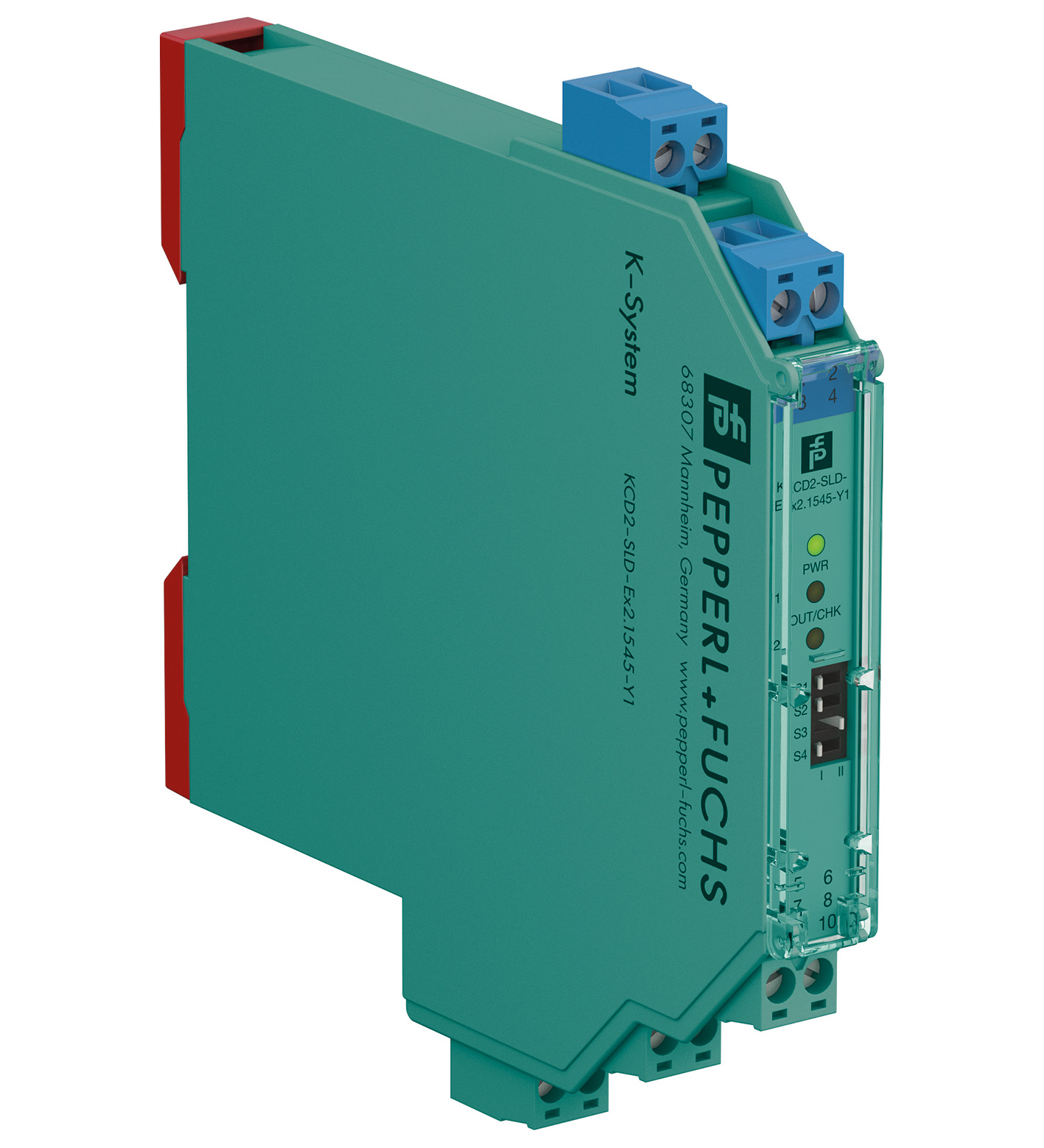
Solenoid Driver. 2-channel isolated barrier, 24 V DC supply (bus or loop powered), Output 45 mA at 15 V DC, Line fault transparency (LFT), Test pulse immunity, Housing width 12.5 mm, Housing width: 12...
Solenoid Driver. 2-channel isolated barrier, 24 V DC supply (bus or loop powered), Output 45 mA at 15 V DC, Line fault transparency (LFT), Test pulse immunity, Housing width 12.5 mm, Housing width: 12.5 mm, Number of channels: 2-channel, Line fault transparency, Rated voltage: 18 ... 30 V DC, Type: logic input, Type [2]: field device supply, Test pulse immunity, Field device: 2 x Valve, Field device [2]: 2 x audible alarm, Field device [3]: 2 x visual alarm, Line fault detection, Current: ≤ 45 mA, Voltage: ≥ 15 V. Signal type: Digital Output. Connection: Power Rail or terminals 9+, 10- bus powered. Rated voltage: 18 ... 30 V DC. Power dissipation: < 2 W. Power consumption: max. 3.5 W at 45 mA output current. Connection side: control side. Connection: terminals 5+, 6-; 7+, 8- limited electrical values : max. 30 V , max. 5 A. Test pulse length: max. 2 ms from DO card. Signal level: loop powered 1-signal: 18 ... 30 V DC (current limited to ≥ 20 mA) 0-signal: 0 ... 5 V DC bus powered 1-signal: 15 ... 24 V DC (current limited at 5 mA)0-signal: 0 ... 5 V DC. Rated current: loop powered 0-signal: typ. 1.6 mA at 1.5 V DC; typ. 8 mA at 3 V DC (maximum leakage current DO card) 1-signal: ≥ 20 mA (minimum load current DO card) bus powered 1-signal: 5 mA. Inrush current: ≤ 200 mA after 100 µs. Connection side: field side. Connection: terminals 1+, 2-; 3+, 4-. Internal resistor: approx. 167 Ω. Current: ≤ 45 mA. Voltage: ≥ 15 V. Current limit: 45 mA. Open loop voltage: min. 23.6 V. Load: nominal 0.05 ... 20 kΩ , valid range for line fault detection (LFD). Energized/De-energized delay: ≤ 20 ms / ≤ 20 ms. Line fault detection: . Test currentmax. 350 µA , calculated by ILFD = 3.3 V / (10 kΩ + RLoad): . Test current: max. 350 µA , calculated by ILFD = 3.3 V / (10 kΩ + RLoad). Input/Output: reinforced insulation according to IEC/EN 61010-1, rated insulation voltage 300 Veff. Power supply/Output: reinforced insulation according to IEC/EN 61010-1, rated insulation voltage 300 Veff. Display elements: LEDs. Control elements: DIP switch. Configuration: via DIP switches. Labeling: space for labeling at the front. Electromagnetic compatibility: . Directive 2014/30/EUEN 61326-1:2013 (industrial locations): . Directive 2014/30/EU: EN 61326-1:2013 (industrial locations). Electromagnetic compatibility: NE 21:2017 , EN IEC 61326-1:2021 (industrial locations) , EN IEC 61326-3-2:2018 For further information see system description.. Degree of protection: IEC 60529:2013. Protection against electrical shock: UL 61010-1:2019. Ambient temperature: -40 ... 70 °C (-40 ... 158 °F). Degree of protection: IP20. Connection: screw terminals. Mass: approx. 105 g. Dimensions: 12.5 x 119 x 114 mm (0.5 x 4.7 x 4.5 inch) (W x H x D) , housing type A2. Mounting: on 35 mm DIN mounting rail acc. to EN 60715:2001. EU-type examination certificate: UL 23 ATEX 3027 X. Marking II (1)G [Ex ia Ga] IIC [exsign] II (1)D [Ex ia Da] IIIC [exsign] I (M1) [Ex ia Ma] IOutputEx ia Refer to certificate for alternative parameters.VoltageUo25.3 VCurrentIo52 mAPowerPo850 mW (angular characteristic curve)Internal resistanceRi167 Ω: . Marking: II (1)G [Ex ia Ga] IIC [exsign] II (1)D [Ex ia Da] IIIC [exsign] I (M1) [Ex ia Ma] I. Output: Ex ia Refer to certificate for alternative parameters.. Voltage: 25.3 V. Current: 52 mA. Power: 850 mW (angular characteristic curve). Internal resistance: 167 Ω. Supply: . Maximum safe voltageUm250 V (Attention! The rated voltage can be lower.): Um. Maximum safe voltage: 250 V (Attention! The rated voltage can be lower.). Input: . Maximum safe voltageUm250 V (Attention! The rated voltage can be lower.): Um. Maximum safe voltage: 250 V (Attention! The rated voltage can be lower.). Collective error message: . Maximum safe voltageUm250 V (Attention! The rated voltage can be lower.): Um. Maximum safe voltage: 250 V (Attention! The rated voltage can be lower.). Certificate: UL 23 ATEX 3065 X. Marking II 3G Ex ec IIC T4 Gc: . Marking: II 3G Ex ec IIC T4 Gc. Galvanic isolation: . Input/Outputsafe electrical isolation acc. to IEC/EN 60079-11, rated insulation voltage 300 VrmsOutput/power supplysafe electrical isolation acc. to IEC/EN 60079-11, rated insulation voltage 300 Vrms: . Input/Output: safe electrical isolation acc. to IEC/EN 60079-11, rated insulation voltage 300 Vrms. Output/power supply: safe electrical isolation acc. to IEC/EN 60079-11, rated insulation voltage 300 Vrms. Directive conformity: . Directive 2014/34/EUEN IEC 60079-0:2018+AC:2020 , EN 60079-7:2015+A1:2018 , EN 60079-11:2012: . Directive 2014/34/EU: EN IEC 60079-0:2018+AC:2020 , EN 60079-7:2015+A1:2018 , EN 60079-11:2012. UL approval: E106378. Control drawing116-0496 (cULus): . Control drawing: 116-0496 (cULus). IECEx approval: . IECEx certificateIECEx ULD 23.0016XIECEx marking[Ex ia Ga] IIC , [Ex ia Da] IIIC , [Ex ia Ma] I Ex ec IIC T4 Gc: . IECEx certificate: IECEx ULD 23.0016X. IECEx marking: [Ex ia Ga] IIC , [Ex ia Da] IIIC , [Ex ia Ma] I Ex ec IIC T4 Gc. Supplementary information: Observe the certificates, declarations of conformity, instruction manuals, and manuals where applicable. For information see www.pepperl-fuchs.com.
| Brand | Pepperl Fuchs |
| Lifecycle status | active |