KCD2-STC-Ex1
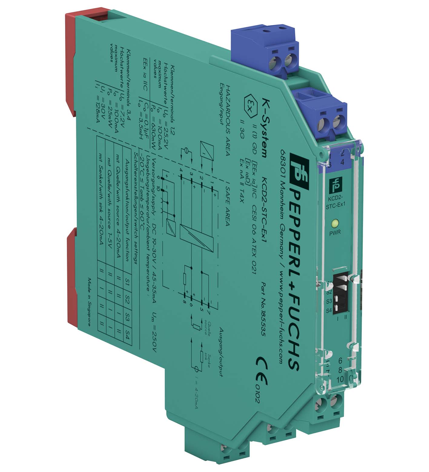
SMART Transmitter Power Supply. 1-channel isolated barrier, 24 V DC supply (Power Rail), Input for 2-wire SMART transmitters and current sources, Output for 4 mA ... 20 mA or 1 V ... 5 V, Housing widt...
SMART Transmitter Power Supply. 1-channel isolated barrier, 24 V DC supply (Power Rail), Input for 2-wire SMART transmitters and current sources, Output for 4 mA ... 20 mA or 1 V ... 5 V, Housing width 12.5 mm, Up to SIL 2 (SC 3) acc. to IEC/EN 61508, Housing width: 12.5 mm, Number of channels: 1-channel, HART communication, Safety Integrity Level (SIL): SIL 2, Systematic capability (SC): SC 3, Rated voltage: 19 ... 30 V DC, Field device: 2-wire transmitter, Field device [2]: current source, Signal: 0/4 ... 20 mA. Signal type: Analog input. Safety Integrity Level (SIL): SIL 2. Systematic capability (SC): SC 3. Connection: Power Rail or terminals 9+, 10-. Rated voltage: 19 ... 30 V DC. Ripple: ≤ 10 %. Rated current: ≤ 45 mA at 24 V and 20 mA source mode output. Power dissipation: ≤ 800 mW. Power consumption: ≤ 1.1 W. Connection side: field side. Connection: terminals 1+, 2-; 3+, 4-. Input signal: 4 ... 20 mA limited to approx. 26 mA. Open circuit voltage/short-circuit current: terminals 1+, 2-: 22 V / 26 mA. Voltage drop: terminals 3+, 4- : approx. 5 V. Available voltage: terminals 1+, 2-: ≥ 15 V at 20 mA ; ≥ 18 V at 4 mA. Connection side: control side. Connection: terminals 5-, 6+ terminals 5-, 8+ for HART resistor. Load: 0 ... 350 Ω (source mode). Output signal: source mode: 4 ... 20 mA or 1 ... 5 V (internal resistor: 250 Ω, 0.1 %) sink mode: 4 ... 20 mA, operating voltage 10 ... 30 V For additional internal or external loads (e. g. terminal +8) the voltage drop has to be considered, e. g. 250 Ω x 20 mA = 5 V.. Ripple: 20 mV rms. Deviation: at 20 °C (68 °F) < 0.1 % of full scale, incl. non-linearity and hysteresis (source mode and sink mode 4 ... 20 mA) ≤ ± 0.2 % incl. non-linearity and hysteresis (source mode 1 ... 5 V). Influence of ambient temperature< 2 µA/K (-20 ... 70 °C (-4 ... 158 °F)); < 4 µA/K (-40 ... -20 °C (-40 ... -4 °F)) (source mode and sink mode 4 ... 20mA)< 0.5 mV/K (-20 ... 70 °C (-4 ... 158 °F)); < 1 mV/K (-40 ... -20 °C (-40 ... -4 °F)) (source mode 1...5 V): . Influence of ambient temperature: < 2 µA/K (-20 ... 70 °C (-4 ... 158 °F)); < 4 µA/K (-40 ... -20 °C (-40 ... -4 °F)) (source mode and sink mode 4 ... 20mA)< 0.5 mV/K (-20 ... 70 °C (-4 ... 158 °F)); < 1 mV/K (-40 ... -20 °C (-40 ... -4 °F)) (source mode 1...5 V). Frequency range: field side into the control side: bandwidth with 0.5 Vpp signal 0 ... 3 kHz (-3 dB) control side into the field side: bandwidth with 0.5 Vpp signal 0 ... 3 kHz (-3 dB). Settling time: ≤ 50 ms. Rise time/fall time: ≤ 10 ms. Input/Output: basic insulation according to IEC/EN 61010-1, rated insulation voltage 300 Veff. Input/power supply: reinforced insulation according to IEC/EN 61010-1, rated insulation voltage 300 Veff. Output/power supply: basic insulation according to IEC/EN 61010-1, rated insulation voltage 300 Veff. Display elements: LED. Control elements: DIP switch. Configuration: via DIP switches. Labeling: space for labeling at the front. Electromagnetic compatibility: . Directive 2014/30/EUEN 61326-1:2013 (industrial locations): . Directive 2014/30/EU: EN 61326-1:2013 (industrial locations). Electromagnetic compatibility: NE 21:2017 EN 61326-3-2:2018. Degree of protection: IEC 60529:2001. Protection against electrical shock: UL 61010-1:2019. Ambient temperature: -40 ... 70 °C (-40 ... 158 °F). Degree of protection: IP20. Connection: screw terminals. Mass: approx. 100 g. Dimensions: 12.5 x 119 x 114 mm (0.5 x 4.7 x 4.5 inch) (W x H x D) , housing type A2. Height124 mmWidth12.5 mmDepth114 mm: . Height: 124 mm. Width: 12.5 mm. Depth: 114 mm. Mounting: on 35 mm DIN mounting rail acc. to EN 60715:2001. EU-type examination certificate: CESI 06 ATEX 021 X. Marking II (1)G [Ex ia Ga] IIC [exsign] II (1)D [Ex ia Da] IIIC [exsign] I (M1) [Ex ia Ma] IInputEx ia: . Marking: II (1)G [Ex ia Ga] IIC [exsign] II (1)D [Ex ia Da] IIIC [exsign] I (M1) [Ex ia Ma] I. Input: Ex ia. Supply: . Maximum safe voltageUm250 V AC (Attention! Um is no rated voltage.): Um. Maximum safe voltage: 250 V AC (Attention! Um is no rated voltage.). Equipment: terminals 1+, 2-. VoltageUo25.2 VCurrentIo100 mAPowerPo630 mWInternal capacitanceCi5.7 nFInternal inductanceLinegligible: Uo. Voltage: 25.2 V. Current: 100 mA. Power: 630 mW. Internal capacitance: 5.7 nF. Internal inductance: negligible. Equipment: terminals 3+, 4-. VoltageUi30 VCurrentIi128 mAPowerPi1000 mWVoltageUo7.2 VCurrentIo100 mAPowerPo25 mWInternal capacitanceCi5.7 nFInternal inductanceLinegligible: Ui. Voltage: 30 V. Current: 128 mA. Power: 1000 mW. Voltage: 7.2 V. Current: 100 mA. Power: 25 mW. Internal capacitance: 5.7 nF. Internal inductance: negligible. Certificate: CESI 19 ATEX 021 X. Marking II 3G Ex ec IIC T4 Gc: . Marking: II 3G Ex ec IIC T4 Gc. Galvanic isolation: . Input/Outputsafe electrical isolation acc. to IEC/EN 60079-11, voltage peak value 375 VInput/power supplysafe electrical isolation acc. to IEC/EN 60079-11, voltage peak value 375 V: . Input/Output: safe electrical isolation acc. to IEC/EN 60079-11, voltage peak value 375 V. Input/power supply: safe electrical isolation acc. to IEC/EN 60079-11, voltage peak value 375 V. Directive conformity: . Directive 2014/34/EUEN IEC 60079-0:2018 , EN 60079-11:2012 , EN IEC 60079-7:2015+A1:2018: . Directive 2014/34/EU: EN IEC 60079-0:2018 , EN 60079-11:2012 , EN IEC 60079-7:2015+A1:2018. FM approval: . FM certificateFM 18 CA 0116 X , FM 19 US 0117 XControl drawing116-0469 (cFMus): . FM certificate: FM 18 CA 0116 X , FM 19 US 0117 X. Control drawing: 116-0469 (cFMus). UL approval: E106378. Control drawing116-0459 (cULus): . Control drawing: 116-0459 (cULus). IECEx approval: . IECEx certificateIECEx CES 06.0001XIECEx marking[Ex ia Ga] IIC , [Ex ia Da] IIIC , [Ex ia Ma] I Ex ec IIC T4 Gc: . IECEx certificate: IECEx CES 06.0001X. IECEx marking: [Ex ia Ga] IIC , [Ex ia Da] IIIC , [Ex ia Ma] I Ex ec IIC T4 Gc. Supplementary information: Observe the certificates, declarations of conformity, instruction manuals, and manuals where applicable. For information see www.pepperl-fuchs.com.
| Brand | Pepperl Fuchs |
| Lifecycle status | active |