KFD2-ER-Ex1.W.LB
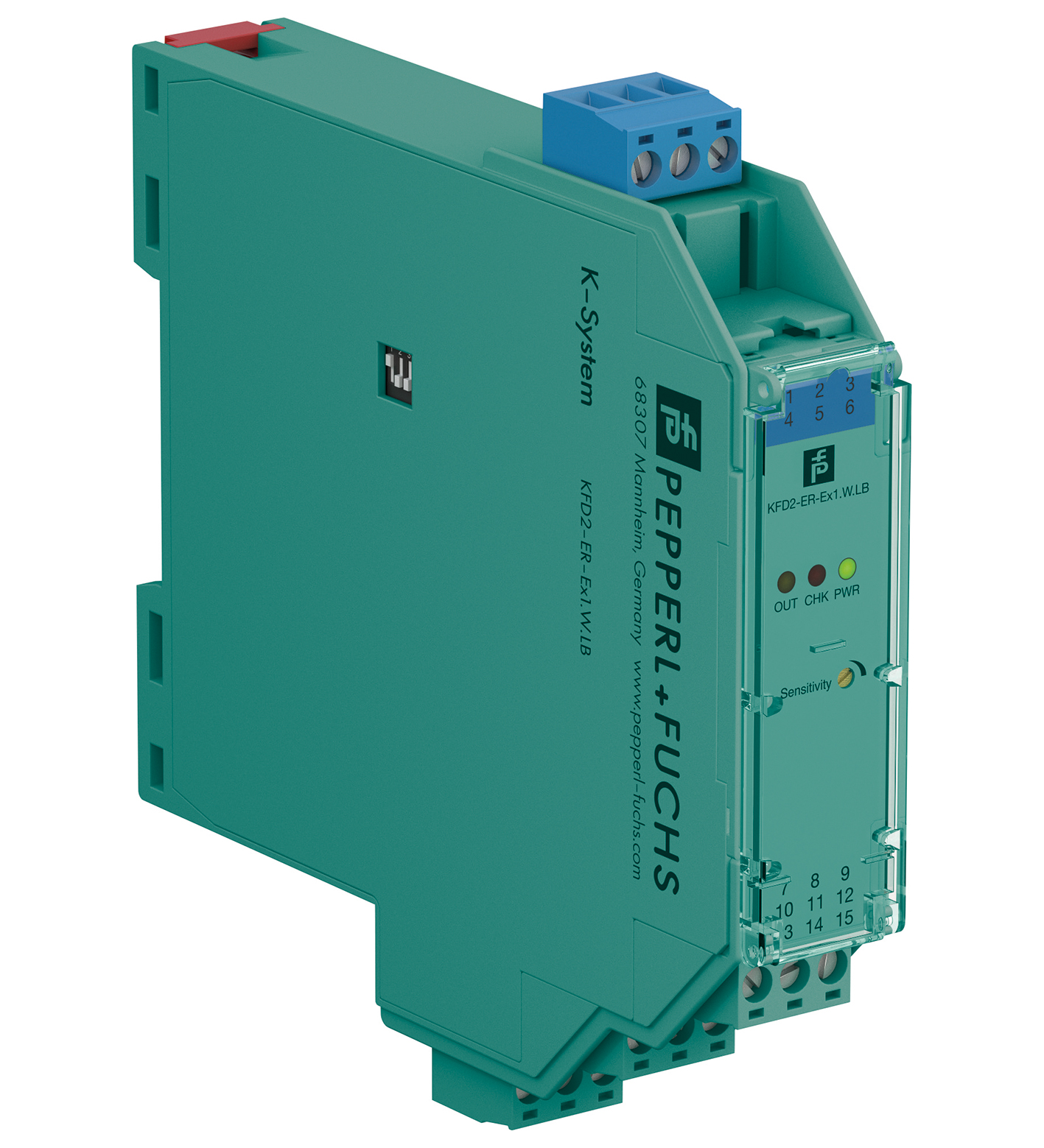
Conductive Switch Amplifier. 1-channel isolated barrier, 24 V DC supply (Power Rail), Level sensing input, Adjustable range 1 kΩ ... 150 kΩ, Relay contact output, Fault relay contact output, Adjustabl...
Conductive Switch Amplifier. 1-channel isolated barrier, 24 V DC supply (Power Rail), Level sensing input, Adjustable range 1 kΩ ... 150 kΩ, Relay contact output, Fault relay contact output, Adjustable time delay up to 10 s, Minimum/maximum control, Line fault detection (LFD), Housing width: 20 mm, Number of channels: 1-channel, Conductivity measurement, Min./max. control, Time delay, Rated voltage: 20 ... 30 V DC, Signal: Resistance, Line fault detection, Type: 2 x relay (change-over contact), Fault indication output. Signal type: Digital Input. Connection: Power Rail or terminals 14+, 15-. Rated voltage: 20 ... 30 V DC. Rated current: 30 ... 40 mA. Connection side: field side. Connection: terminals 1 (mass), 2 (min), 3 (max). Control input: min./max. control system: terminals 1, 2, 3on/off control system: terminals 1, 3. Response sensitivity: 1 ... 150 kΩ , adjustable via potentiometer. Connection side: control side. Connection: terminals 7, 8, 9; 10, 11, 12. Switching power: max. 192 W , 2000 VA. Output: signal ; relay. Contact loading: 253 V AC/2 A/cos φ > 0.7; 40 V DC/2 A resistive load. Time constant for signal damping: 0.5 s, 2 s, 5 s, 10 s. Input/Output: reinforced insulation according to IEC/EN 61010-1, rated insulation voltage 300 Veff. Input/power supply: reinforced insulation according to IEC/EN 61010-1, rated insulation voltage 300 Veff. Output/power supply: reinforced insulation according to IEC/EN 61010-1, rated insulation voltage 300 Veff. Display elements: LEDs. Control elements: DIP switch potentiometer. Configuration: via DIP switches via potentiometer. Labeling: space for labeling at the front. Electromagnetic compatibility: . Directive 2014/30/EUEN 61326-1:2013 (industrial locations): . Directive 2014/30/EU: EN 61326-1:2013 (industrial locations). Low voltage: . Directive 2014/35/EUEN 61010-1:2010: . Directive 2014/35/EU: EN 61010-1:2010. Electromagnetic compatibility: NE 21:2006. Degree of protection: IEC 60529:2001. Ambient temperature: -20 ... 60 °C (-4 ... 140 °F). Degree of protection: IP20. Connection: screw terminals , max. 2.5 mm2. Mass: approx. 150 g. Dimensions: 20 x 119 x 115 mm (0.8 x 4.7 x 4.5 inch) (W x H x D) , housing type B2. Height119 mmWidth20 mmDepth115 mm: . Height: 119 mm. Width: 20 mm. Depth: 115 mm. Mounting: on 35 mm DIN mounting rail acc. to EN 60715:2001. EU-type examination certificate: DMT 00 ATEX E 033. Marking II (1)G [EEx ia] IIC [circuit(s) in zone 0/1/2]Input[EEx ia] IICVoltageUo10 VCurrentIo2.5 mAPowerPo6 mW: . Marking: II (1)G [EEx ia] IIC [circuit(s) in zone 0/1/2]. Input: [EEx ia] IIC. Voltage: 10 V. Current: 2.5 mA. Power: 6 mW. Supply: . Maximum safe voltageUm40 V DC (Attention! Um is no rated voltage.): Um. Maximum safe voltage: 40 V DC (Attention! Um is no rated voltage.). Output: . Contact loading253 V AC/2 A/cos φ > 0.7; 40 V DC/2 A resistive load: . Contact loading: 253 V AC/2 A/cos φ > 0.7; 40 V DC/2 A resistive load. Galvanic isolation: . Input/Outputsafe electrical isolation acc. to IEC/EN 60079-11, voltage peak value 375 VInput/power supplysafe electrical isolation acc. to IEC/EN 60079-11, voltage peak value 375 V: . Input/Output: safe electrical isolation acc. to IEC/EN 60079-11, voltage peak value 375 V. Input/power supply: safe electrical isolation acc. to IEC/EN 60079-11, voltage peak value 375 V. Directive conformity: . Directive 2014/34/EUEN 60079-0:2012+A11:2013, EN 60079-11:2012: . Directive 2014/34/EU: EN 60079-0:2012+A11:2013, EN 60079-11:2012. Supplementary information: Observe the certificates, declarations of conformity, instruction manuals, and manuals where applicable. For information see www.pepperl-fuchs.com.
| Brand | Pepperl Fuchs |
| Lifecycle status | active |