KFD2-RSH-1.2D.FL2
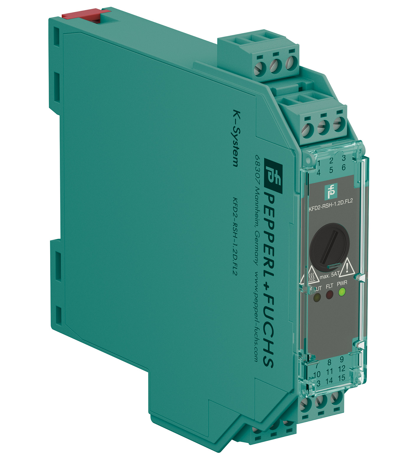
Relay Module. 1-channel signal conditioner, 24 V DC supply, Logic input 19 V DC ... 26.4 V DC, Recommended connectable voltage 8 V DC ... 60 V DC, Relay contact output for de-energized to safe functio...
Relay Module. 1-channel signal conditioner, 24 V DC supply, Logic input 19 V DC ... 26.4 V DC, Recommended connectable voltage 8 V DC ... 60 V DC, Relay contact output for de-energized to safe function, Line fault transparency (LFT), Diagnostic function, Up to SIL 3 acc. to IEC/EN 61508, Up to PL e acc. to EN/ISO 13849, Housing width: 20 mm, Number of channels: 1-channel, Diagnostics function, Line fault transparency, DTS function (de-energized to safe), Safety Integrity Level (SIL): SIL 3. Signal type: Digital Output. Safety Integrity Level (SIL): SIL 3. Systematic capability (SC): SC 3. Performance level (PL): PL e. Connection: Power Rail or terminals 14+, 15-. Rated voltage: 19 ... 26.4 V DC. Input current: max. 35 mA at 24 V DC , max. 44 mA at 19 V DC , with enabled internal fault detection. Power consumption: < 1.7 W , includes the power consumption of the digital input , see derating curves. Connection side: control side. Connection: terminals 7+, 8-. Pulse/Pause ratio: min. 150 ms / min. 150 ms with disabled internal fault detection min. 1 s / min. 1 s with enabled internal fault detection. Test pulse length: max. 2 ms from DO card. Signal level: 0-signal: -5 ... 5 V DC 1-signal: 19 ... 26.4 V DC. Rated current: 0-signal: typ. 1.6 mA at 1.5 V DC; typ. 8 mA at 3 V DC (maximum leakage current DO card) 1-signal: ≥ 36 mA (minimum load current DO card). Inrush current: < 200 mA after 100 µs. Connection side: field side. Connection: external voltage : terminals 4+, 5+, 2- load : terminals 6, 3. Connectable voltage: 8 ... 60 V DC. Power dissipation: < 3.3 W at 5 A , see derating curves. Contact loading: 30 V DC / 5 A resistive load , see derating curves. Minimum switch current: 10 mA. Mechanical life: 5 x 10⁶ switching cycles. Line fault detection: low voltage < 5 V DC undercurrent: 10 mA DC; overcurrent: 2.2 A DC (relay energized) breakage: 8.2 kΩ; short-circuit: 11 Ω (load, relay de-energized). Fuse rating: 2.5 A (scope of delivery)max. 5 AT, recommended maximum utilization of the fuse: 80 %. Connection: terminals 10, 11. Contact loading: 30 V DC/ 0.5 A resistive load. Reaction time: < 2 s. Mechanical life: 105 switching cycles. Switching frequency: < 3 Hz with disabled internal fault detection < 0.5 Hz with enabled internal fault detection. Input/power supply: basic insulation according to IEC/EN 61010-1, rated insulation voltage 60 Veff. Input/fault indication output: basic insulation according to IEC/EN 61010-1, rated insulation voltage 30 Veff. Output/other circuits: reinforced insulation according to IEC/EN 61010-1, rated insulation voltage 300 Veff. Display elements: LEDs. Control elements: DIP switch. Configuration: via DIP switches. Labeling: space for labeling at the front. Electromagnetic compatibility: . Directive 2014/30/EUEN 61326-1:2013 (industrial locations): . Directive 2014/30/EU: EN 61326-1:2013 (industrial locations). Machinery Directive: . Directive 2006/42/ECEN 62061:2005+AC:2010+A1:2013+A2:2015 , EN/ISO 13849-1:2015: . Directive 2006/42/EC: EN 62061:2005+AC:2010+A1:2013+A2:2015 , EN/ISO 13849-1:2015. Electromagnetic compatibility: NE 21:2017 , IEC/EN 61326-3-2:2018 , EN 61326-3-1:2017. Degree of protection: IEC 60529:2013. Protection against electrical shock: EN 61010-1:2010. Ambient temperature: -20 ... 60 °C (-4 ... 140 °F) Observe the temperature range limited by derating, see section derating.. Degree of protection: IP20. Connection: screw terminals. Mass: approx. 142 g. Dimensions: 20 x 119 x 115 mm (0.8 x 4.7 x 4.5 inch) (W x H x D) , housing type B2. Mounting: on 35 mm DIN mounting rail acc. to EN 60715:2001. Supplementary information: Observe the certificates, declarations of conformity, instruction manuals, and manuals where applicable. For information see www.pepperl-fuchs.com.
| Brand | Pepperl Fuchs |
| Lifecycle status | active |