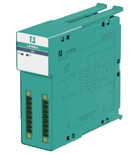
LB1008A
Digital Input. 8-channel, Dry contact or NAMUR inputs, Installation in Zone 2 or safe area, Positive or negative logic selectable, Explosion protection: Ex ic, Connection: NAMUR sensor, Connection [2]...
Digital Input. 8-channel, Dry contact or NAMUR inputs, Installation in Zone 2 or safe area, Positive or negative logic selectable, Explosion protection: Ex ic, Connection: NAMUR sensor, Connection [2]: volt-free contact. Occupied slots: 2. Connection: backplane bus. Rated voltage: 12 V DC , only in connection with the power supplies LB9***. Power dissipation: 0.95 W. Power consumption: 0.95 W. Connection: backplane bus. Interface: manufacturer-specific bus to standard com unit. Number of channels: 8. Sensor interface: . ConnectionNAMUR sensorConnection [2]volt-free contactConnection [3]Usage without connection to areas where there is a risk of explosion: active signals, mechanical contacts, NAMUR sensors, 2-wire sensors If the device has been operated in general electrical systems that are not connected to areas where there is a risk of explosion, the device cannot then be used in electrical systems that are connected to areas where there is a risk of explosion. Usage with connection to areas where there is a risk of explosion: mechanical contacts, NAMUR sensors: . Connection: NAMUR sensor. Connection [2]: volt-free contact. Connection [3]: Usage without connection to areas where there is a risk of explosion: active signals, mechanical contacts, NAMUR sensors, 2-wire sensors If the device has been operated in general electrical systems that are not connected to areas where there is a risk of explosion, the device cannot then be used in electrical systems that are connected to areas where there is a risk of explosion. Usage with connection to areas where there is a risk of explosion: mechanical contacts, NAMUR sensors. Connection: channel I: 1+, 2-; channel II: 3+, 4-; channel III: 5+, 6-; channel IV: 7+, 8-; channel V: 9+, 10-; channel VI: 11+, 12-; channel VII: 13+, 14-; channel VIII: 15+, 16-. Rated values: acc. to EN 60947-5-6 (NAMUR). Switching point/switching hysteresis: 1.2 ... 2.1 mA / ± 0.2 mA. Voltage: 8.2 V. Internal resistor: 1 kΩ. Line fault detection: can be switched on/off for each channel via configuration tool , active signals (24 V, 5 V) without line fault detection. Connectionmechanical switch with additional resistors (see connection diagram) proximity sensors without additional wiringShort-circuit< 360 ΩOpen-circuit< 0.35 mA: . Connection: mechanical switch with additional resistors (see connection diagram) proximity sensors without additional wiring. Short-circuit: < 360 Ω. Open-circuit: < 0.35 mA. Digital signals (active): Use in safe area: configurable 24 V 5 V. Switching point: ON> 8 V > 2.7 VSwitching point: OFF< 3 V < 2.3 V: . Switching point: ON: > 8 V > 2.7 V. Switching point: OFF: < 3 V < 2.3 V. Minimum pulse duration: 1 ms. LED indication: Power LED (P) green: supply Status LED (I) red: line fault. Coding: optional mechanical coding via front socket. Electromagnetic compatibility: . Directive 2014/30/EUEN 61326-1:2013: . Directive 2014/30/EU: EN 61326-1:2013. Electromagnetic compatibility: NE 21. Degree of protection: IEC 60529. Environmental test: EN 60068-2-14. Shock resistance: EN 60068-2-27. Vibration resistance: EN 60068-2-6. Damaging gas: EN 60068-2-42. Relative humidity: EN 60068-2-78. Ambient temperature: -20 ... 60 °C (-4 ... 140 °F). Storage temperature: -40 ... 85 °C (-40 ... 185 °F). Relative humidity: 95 % non-condensing. Altitude: max. 2000 m. Shock resistance: shock type I, shock duration 11 ms, shock amplitude 15 g, number of shocks 18. Vibration resistance: frequency range 10 ... 150 Hz; transition frequency: 57.56 Hz, amplitude/acceleration ± 0.075 mm/1 g; 10 cyclesfrequency range 5 ... 100 Hz; transition frequency: 13.2 Hz amplitude/acceleration ± 1 mm/0.7 g; 90 minutes at each resonance. Damaging gas: designed for operation in environmental conditions acc. to ISA-S71.04-1985, severity level G3. Degree of protection: IP20 when mounted on backplane. Connection: removable front connector with screw flange (accessory)wiring connection via spring terminals (0.14 ... 1.5 mm2) or screw terminals (0.08 ... 1.5 mm2). Mass: approx. 130 g. Dimensions: . Height100 mmWidth32.5 mmDepth102 mm: . Height: 100 mm. Width: 32.5 mm. Depth: 102 mm. Certificate: PF 08 CERT 1234 X. Marking II 3 G Ex nA [ic] IIC T4 Gc: . Marking: II 3 G Ex nA [ic] IIC T4 Gc. Galvanic isolation: . Input/power supply, internal bussafe electrical isolation acc. to EN 60079-11, voltage peak value 375 V: . Input/power supply, internal bus: safe electrical isolation acc. to EN 60079-11, voltage peak value 375 V. Directive conformity: . Directive 2014/34/EUEN IEC 60079-0:2018+AC:2020 EN 60079-11:2012 EN 60079-15:2010: . Directive 2014/34/EU: EN IEC 60079-0:2018+AC:2020 EN 60079-11:2012 EN 60079-15:2010. IECEx approval: . IECEx certificateIECEx BVS 09.0037XIECEx markingEx nA [ic] IIC T4 Gc: . IECEx certificate: IECEx BVS 09.0037X. IECEx marking: Ex nA [ic] IIC T4 Gc. System information: The module has to be mounted in appropriate backplanes (LB9***) in Zone 2 or outside hazardous areas. Here, observe the corresponding declaration of conformity. For use in hazardous areas (e. g. Zone 2 or Zone 22) the module must be installed in an appropriate enclosure.. Supplementary information: EC-Type Examination Certificate, Statement of Conformity, Declaration of Conformity, Attestation of Conformity and instructions have to be observed where applicable. For information see www.pepperl-fuchs.com.
| Brand | Pepperl Fuchs |
| Lifecycle status | active |