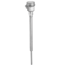
LVL-B2
Vibration Limit Switch. Limit switch for bulk solids, Device with tube extension, No calibration: easy commissioning (plug and play), Insensitive to build-up: maintenance-free operation, No mechanical...
Vibration Limit Switch. Limit switch for bulk solids, Device with tube extension, No calibration: easy commissioning (plug and play), Insensitive to build-up: maintenance-free operation, No mechanically moving parts: no wear, long operating life, Sensor material stainless steel: hardly any abrasion even with building materials, Insensitive to external vibration and flow noises. Measuring method: A piezoelectric drive excites the vibrating rod of the device to its resonance frequency. If medium covers the vibrating rod, the rod's vibrating amplitude changes (the vibration is damped). The electronics of the device compare the actual amplitude with a target value and indicates whether the vibrating rod is vibrating freely or whether it is covered by medium.. Equipment architecture: The measuring system consists of:- the device with electronic insert- a supply point- the connected control systems, switching units, signalling systems (e. g. lamps, horns, PCS, PLC, etc.). Construction type: device with tube extension. Operating mode: MAX = maximum safety:The device switches if the probe is covered or if the supply voltage is disconnected in a safety-oriented manner (signal on alarm).example application: overspill protectionMIN = minimum safety:The device switches if the probe is uncovered or if the supply voltage is disconnected in a safetyoriented manner (signal on alarm).example application: dry-running protection. Series: Vibracon LVL-B2. Rated voltage: electronic insert FEM22 (E5): 10 ... 45 V DCelectronic insert FEM24 (WA): 19 ... 253 V AC, 50/60 Hz or 19 ... 55 V DC. Ripple: electronic insert FEM22 (E5): max. 5 V, 0 ... 400 Hz. Current consumption: electronic insert FEM22 (E5): max. 18 mA. Power consumption: electronic insert FEM22 (E5): max. 0.81 Welectronic insert FEM 24 (WA): max. 1.3 W. Reverse polarity protection: separation voltage 2.2 kV. Surge protection: electronic insert FEM22 (E5) : overvoltage category III. Input signal: probe covered - small amplitudeprobe not covered - large amplitude. Measured variable: level (according to the mounting location and the overall length). Measuring range: The measuring range depends on the mounting location of the device and the length of the pipe extension selected.The pipe extension is available in the following lengths: 500 mm, 1000 mm, 1500 mm, 20 inch, 40 inch, 60 inch. Load: electronic insert FEM22 (E5):- load switched via transistor and separate PNP connection- load current: max. 45 V (cyclical overload and short-circuit protection), continuous max. 350 mA- residual current: < 100 µA (for blocked transistor)- capacitive load: max. 0.5 µF for 45 V, max. 1.0 µF for 24 V- residual voltage: < 3 V (for transistor switched through) electronic insert FEM24 (WA):- loads switched via 2 floating change-over contacts- version AC: I max. 6 A, U max. 253 V; P max. 1500 VA, cos φ = 1, P max. 750 VA, cos φ > 0.7- version DC: I max. 6 A to 30 V, I max. 0.2 A to 125 V- the following applies when connecting a functional extra-low voltage circuit with double insulation as per IEC 1010: sum of voltages of relay output and power supply max. 300 V. Switch-on delay: correct switching after max. 3 s. Output signal: digital. Signal on alarm: electronic insert FEM22 (E5): output signal on power failure or in the event of device failure - < 100 µAelectronic insert FEM24 (WA): output signal in event of power failure - relay de-energised. Input/power supply: electronic insert FEM22 (E5). Input/Other circuits: electronic insert FEM24 (WA). Electromagnetic compatibility: . Directive 2014/30/EUEN 61326-1:2006 , EN 61326-2-3:2006: . Directive 2014/30/EU: EN 61326-1:2006 , EN 61326-2-3:2006. Low voltage: . Directive 2014/35/EUelectronic insert FEM24 (WA) : EN 61010-1:2010: . Directive 2014/35/EU: electronic insert FEM24 (WA) : EN 61010-1:2010. Electromagnetic compatibility: NE 21. Degree of protection: IEC 60529:2001. Vibration resistance: EN 60068-2-27. Climate class: EN 60068, part 2-38, fig. 2a. Measuring frequency: 700 ... 800 Hz. Switching time: when covering the sensor approx. 0.5 s, when uncovering the sensor approx. 1.0 s. Installation conditions: . Installation positionsee section mounting position: . Installation position: see section mounting position. Process conditions: . Process temperature-40 ... 150 °C (-40 ... 302 °F)Medium pressure limits-1 ... 25 bar max. working pressure 25 bar, burst pressure 100 barThermal shock resistancemax. 120 KState of aggregationsolidsSolid contents≤ ∅25 mmBulk density≥ 200 g/l, not fluidised: . Process temperature: -40 ... 150 °C (-40 ... 302 °F). Medium pressure limits: -1 ... 25 bar max. working pressure 25 bar, burst pressure 100 bar. Thermal shock resistance: max. 120 K. State of aggregation: solids. Solid contents: ≤ ∅25 mm. Bulk density: ≥ 200 g/l, not fluidised. Ambient temperature: -40 ... 70 °C (-40 ... 158 °F). Storage temperature: -40 ... 85 °C (-40 ... 185 °F). Degree of protection: IP66 / IP67, NEMA 4X. Connection: gland M20thread G1/2, NPT1/2. Material: F16 housing: PTB-FR, cover with transparent glass made of PA12, EPDM cover sealF18 housing: aluminum EN-AC-AlSi10Mg, plastic coatedcover seal: EPDMprocess connections, sensor: stainless steel 1.4435/316L. Mass: device with F16 housing, electronic insert FEM24 (WA) and R1 thread:- 500 mm (20 inch) = approx. 1.3 kg- 1000 mm (40 inch) = approx. 2.0 kg- 1500 mm (60 inch) = approx. 2.6 kg. Dimensions: max. ∅85 mm (3.3 inch), length 160 mm (6.3 inch) + LL = 500 mm, 1000 mm, 1500 mm, 20 inch, 40 inch, 60 inch. Process connection: thread R1, R1-1/2 acc. to DIN 2999thread 1-1/4 - 11-1/2 NPT, 1-1/2 - 11-1/2 NPT acc. to ANSI B 1.20.1. EU-type examination certificate: see instruction manuals. IECEx approval: see instruction manuals. Supplementary documentation: technical information (TI) manuals, brief instructions (BA, KA) instruction manuals. Supplementary information: Observe the certificates, declarations of conformity, instruction manuals, and manuals where applicable. For information see www.pepperl-fuchs.com.. Designation: - LVL-Z200 sliding sleeve for pressurized container- LVL-Z201 sliding sleeve for pressurized container- LVL-Z202 sliding sleeve for unpressurized container- LVL-Z203 sliding sleeve for unpressurized container
| Brand | Pepperl Fuchs |
| Lifecycle status | active |