R4D0-FB-IA*
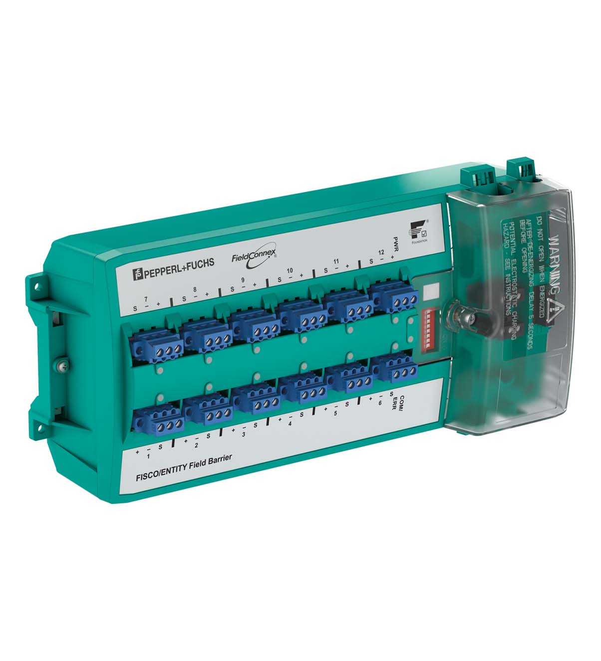
Fieldbus Barrier. Fieldbus barrier, module for DIN rail mounting, 8 ... 12 outputs Ex ia IIC, FISCO and Entity, Advanced fault isolation and diagnostics at the spur, FieldBarrier in Zone 1/Div. 2, Ins...
Fieldbus Barrier. Fieldbus barrier, module for DIN rail mounting, 8 ... 12 outputs Ex ia IIC, FISCO and Entity, Advanced fault isolation and diagnostics at the spur, FieldBarrier in Zone 1/Div. 2, Instruments in Zone 0...1/Div. 1, For FOUNDATION Fieldbus H1 and PROFIBUS PA, IECEx approval, Dust protection, International, Europe, USA, Device coupler location: Zone 2 - high-power trunk<BR>Zone 1 - high-power trunk<BR>Division 2 - high-power trunk<BR>Division 1 - high-power trunk. Design / Mounting: Cabinet installation. Installation in hazardous area: Zone 1 / Div. 2. Power dissipation: see table 1. Main cable (Trunk): . Rated voltage16 ... 32 V DC ,min. 15 V in case of brown outRated currenttrunk IN to trunk OUT max. 2 A see table 1 Cable shield grounding optionCapacitive via 5.7 nF DirectVoltage droptrunk IN to trunk OUT 100 mV max.Number of couplersmax. 3 per segmentReverse polarity protectionBuilt-In: . Rated voltage: 16 ... 32 V DC ,min. 15 V in case of brown out. Rated current: trunk IN to trunk OUT max. 2 A see table 1. Cable shield grounding option: Capacitive via 5.7 nF Direct. Voltage drop: trunk IN to trunk OUT 100 mV max.. Number of couplers: max. 3 per segment. Reverse polarity protection: Built-In. Outputs: . Number of outputs8, 10 or 12Number of devices per output1Cable length120 mRated voltage10 ... 14 VRated currentmax. 43 mA at one spur ,max. 320 mA total current at all spursShort-circuit current53 mA , 1 mA in fallback stateCable shield grounding optionCapacitive via 4.4 nF: . Number of outputs: 8, 10 or 12. Number of devices per output: 1. Cable length: 120 m. Rated voltage: 10 ... 14 V. Rated current: max. 43 mA at one spur ,max. 320 mA total current at all spurs. Short-circuit current: 53 mA , 1 mA in fallback state. Cable shield grounding option: Capacitive via 4.4 nF. Surge protection: Trunk overvoltage protection if voltage exceeds typ. 39 V, max. 41 V. Fault Isolation: Short Circuit Current Limitation at spurs Bounce Protection at spurs Signal inhibit at spurs. Physical Layer Diagnostic: Signal level at spurs Signal jitter at spurs Noise level at spurs. Switch: S1 ON: diagnostic alarms activated S2 ON: diagnostic warnings activated S3-S8: not used. LED PWR: green: Fieldbus voltage > 16 V. LED COM/ERR: yellow flashing: fieldbus communication and physical layer status ,red: Hardware error. LED SPURS: red: 2 Hz flashing in short-circuit condition. Main wire/outputs: isolation is not affected by interference according to EN 60079-11, voltage peak value 375 V. Output/Output: No Isolation. Electromagnetic compatibility: . Directive 2014/30/EUEN 61326-1:2013: . Directive 2014/30/EU: EN 61326-1:2013. Electromagnetic compatibility: NE 21:2011. Degree of protection: IEC/EN 60529. Fieldbus standard: IEC 61158-2. Climatic conditions: IEC 60721. Shock resistance: EN 60068-2-27. Vibration resistance: EN 60068-2-6. Ambient temperature: -40 ... 70 °C (-40 ... 158 °F). Storage temperature: -40 ... 85 °C (-40 ... 185 °F). Relative humidity: < 95 % non-condensing. Shock resistance: 15 g 11 ms. Vibration resistance: 1 g , 10 ... 150 Hz. Corrosion resistance: acc. to ISA-S71.04-1985, severity level G3. Connection type: screw terminal , pluggable or spring terminal , pluggable. Core cross section: see table 2. Housing material: Polycarbonate. Degree of protection: IP20. Mass: 2100 g. Dimensions: see dimensions. Mounting: DIN rail mounting. EU-type examination certificate: BVS 13 ATEX E 121 X. Marking II 2(1)G Ex eb ib mb [ia Ga] IIC T4 Gb [exsign] II (1)D [Ex ia Da] IIIC [exsign] I (M1) [Ex ia Ma] I: . Marking: II 2(1)G Ex eb ib mb [ia Ga] IIC T4 Gb [exsign] II (1)D [Ex ia Da] IIIC [exsign] I (M1) [Ex ia Ma] I. Main cable (Trunk): . Maximum safe voltage Um253 V AC: . Maximum safe voltage Um: 253 V AC. Outputs: in accordance to FISCO and Entity. PowerPo1.063 WVoltageUo17.1 VCurrentIo248.55 mAInductanceLogas group IIC 470 µH ,gas group IIB 2 mHCapacitanceCogas group IIC 367 nF ,gas group IIB 2.15 µF: Po. Power: 1.063 W. Voltage: 17.1 V. Current: 248.55 mA. Inductance: gas group IIC 470 µH ,gas group IIB 2 mH. Capacitance: gas group IIC 367 nF ,gas group IIB 2.15 µF. Directive conformity: . Directive 2014/34/EUEN IEC 60079-0:2018+AC:2020 , EN 60079-7:2015+A1:2018 , EN 60079-11:2012 , EN 60079-18:2015: . Directive 2014/34/EU: EN IEC 60079-0:2018+AC:2020 , EN 60079-7:2015+A1:2018 , EN 60079-11:2012 , EN 60079-18:2015. CSA approval: CSA 14.70004139. Control drawing116-0400Approved forClass I, Division 2, Groups A, B, C, D T4Class I, Zone 1, AEx/Ex e ib mb [ia Ga] IIC T4 GbClass I, Zone 1, AEx/Ex e ib mb [ia IIC Da] IIC T4 GbAssociated equipment for Class I, Division 1 Groups A, B, C, DAssociated equipment for Class II, Division 1 Groups E, F, GAssociated equipment for Class III, Division 1: . Control drawing: 116-0400. Approved for: Class I, Division 2, Groups A, B, C, D T4Class I, Zone 1, AEx/Ex e ib mb [ia Ga] IIC T4 GbClass I, Zone 1, AEx/Ex e ib mb [ia IIC Da] IIC T4 GbAssociated equipment for Class I, Division 1 Groups A, B, C, DAssociated equipment for Class II, Division 1 Groups E, F, GAssociated equipment for Class III, Division 1. IECEx approval: . IECEx certificateIECEx BVS 13.0119XIECEx markingEx eb ib mb [ia Ga] IIC T4 Gb [Ex ia Da] IIIC [Ex ia Ma] I: . IECEx certificate: IECEx BVS 13.0119X. IECEx marking: Ex eb ib mb [ia Ga] IIC T4 Gb [Ex ia Da] IIIC [Ex ia Ma] I. FOUNDATION Fieldbus: FF-846. Supplementary information: EC-Type Examination Certificate, Statement of Conformity, Declaration of Conformity, Attestation of Conformity and instructions have to be observed where applicable. For information see www.pepperl-fuchs.com.
| Brand | Pepperl Fuchs |
| Lifecycle status | active |